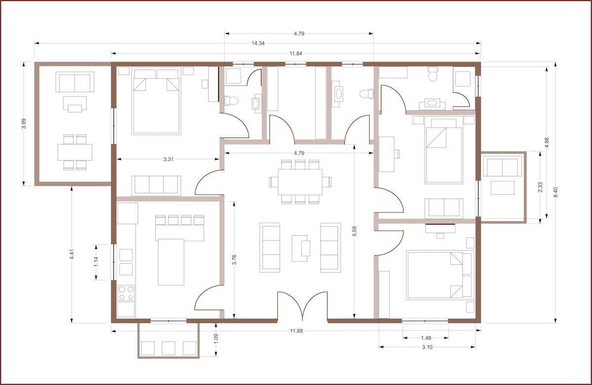

Blueprint symbols are the shorthand a designer uses so a plan sheet doesn’t have to spell everything out. A door is a line with an arc. An outlet is a small circle with two lines through it. A ceiling diffuser is a square with arrows. Learn the common ones and a sheet that looked like noise starts reading like a list of instructions.
One rule first, because it settles most arguments on site: the legend sheet in your plan set is the final word. There’s a national standard for these symbols, but it’s voluntary, and every architect and engineer draws a few of them their own way. The charts below cover what you’ll see most often. The legend tells you what this particular set means.
Start With the Legend Sheet
Every complete plan set has a sheet, or part of a sheet, that lists the symbols and abbreviations used in it. On architectural sets it’s usually near the front with the general notes. The trades often carry their own: the electrical legend sits on the first electrical sheet, the plumbing legend on the first plumbing sheet, and the mechanical legend on the first mechanical sheet.
The industry’s reference is the United States National CAD Standard, published by the National Institute of Building Sciences with the American Institute of Architects and the Construction Specifications Institute. It includes a standard symbols library and the rules for how sheets in a set are organized. Plenty of firms follow it closely. Plenty start from it and change things. That’s why the legend matters more than any chart, this one included.
Two habits save a lot of trouble:
- Keep the legend with the sheets you’re using. If you pull the electrical sheets out of the set for a crew, pull the electrical legend with them.
- Read abbreviations in context. The same two letters can mean different things on different sheets. There’s a short list of the usual troublemakers further down.
Floor Plan Symbols
The architectural floor plan is the sheet every trade starts from, so its symbols are worth knowing cold.
| Symbol | What it looks like | What it means |
|---|---|---|
| Wall | Two parallel lines, often filled or hatched | Hatch or fill patterns usually separate new walls from existing ones and one material from another. Check the legend |
| Wall or partition tag | A small shape with a number or letter | Points to a wall type in the partition schedule, which gives the studs, layers and rating |
| Door | A straight line for the door leaf and a quarter-circle arc for the swing | The arc shows which way the door opens and which side it’s hinged on |
| Door tag | A circle, hexagon or box with a number, near the door | Points to the door schedule for size, type and hardware |
| Window | Thin parallel lines set into the wall | The window sits in the wall at that spot |
| Window tag | A shape with a letter or number near the window | Points to the window schedule for type and size |
| Stairs | Parallel lines for treads, an arrow, and a break line | The arrow is labeled UP or DN from the floor you’re looking at |
| Room tag | Room name with a number, often in a box | The room number ties to the finish schedule |
| Section marker | A circle split by a line, with an arrow or flag | Top number is the drawing number, bottom is the sheet it’s on. The arrow shows which way the section looks |
| Detail callout | A circle with a drawing and sheet number, tied to a boundary around the area | That area is drawn larger on the sheet named in the circle |
| Elevation marker | A circle or shape with one or more pointers | Points to an exterior or interior elevation and the sheet it’s on |
| Column grid | Letters in bubbles one way, numbers the other | Grid lines are how everyone on the job names a location: “at C-4” |
| North arrow | An arrow, often with an N | Orients the plan. Not always straight up the sheet |
| Revision cloud | A scalloped outline with a triangle and number | That area changed in the revision numbered in the triangle |
| Dashed lines | Short dashes | Usually something above or hidden: overhead cabinets, a soffit, a beam. The legend will say |
| Centerline | A long dash, short dash pattern, sometimes marked CL | The center of a wall, column, opening or fixture |
The section, detail and elevation markers are the ones newer folks skip, and they’re the ones that send you to the right sheet. If a bubble reads 3 over A-501, the drawing you want is detail 3 on sheet A-501.
Electrical Symbols
Electrical plans are mostly small symbols scattered across a floor plan, with circuits drawn between them. Here are the ones you’ll see on nearly every set.
| Symbol | What it looks like | What it means |
|---|---|---|
| Duplex receptacle | A small circle with two short parallel lines through it | A standard two-outlet receptacle |
| GFCI receptacle | The receptacle symbol labeled GFI or GFCI | Ground fault protected outlet. Kitchens, baths, garages, exterior |
| Weatherproof receptacle | Receptacle symbol labeled WP | Outlet with a weather-resistant cover |
| Special-purpose outlet | A receptacle symbol with a letter, number or note | A dedicated or higher-voltage outlet. The note or legend gives the details |
| Single-pole switch | The letter S | One switch controls the fixture |
| Three-way switch | S with a small 3 (S3) | Two switches control the same fixture, like at each end of a hall |
| Four-way switch | S with a small 4 (S4) | Used between two three-ways for a third switch location |
| Ceiling light | A circle, often with a letter or tag inside or beside it | The tag points to the light fixture schedule |
| Switch leg | A curved line, often dashed, from switch to fixtures | Shows which switch controls which lights. Not the wire route |
| Home run | A line ending in an arrow, labeled with circuit numbers | The circuit runs back to the panel named on the line |
| Panel | A rectangle, often filled, with a name like LP-1 | Panelboard. The panel schedule lists every circuit |
| Smoke detector | Often a circle labeled SD or SMK | Smoke alarm. Check the legend, because SD can mean other things |
| Data or phone | Often a triangle | Low-voltage outlet for data or phone |
Electrical sheets lean hard on schedules. The light fixture schedule, panel schedules and one-line diagram carry the detail the plan symbols can’t. If a symbol has a tag next to it, there’s a schedule somewhere in the set that explains it.
Plumbing Symbols
Plumbing plans use fixture outlines on the architectural background, plus pipe runs labeled by system.
| Symbol or abbreviation | What it looks like | What it means |
|---|---|---|
| Fixtures | Outlines of the fixture, often tagged | Water closet (WC), lavatory (LAV), urinal (UR), shower (SH). Tags like P-1 point to the plumbing fixture schedule |
| CO | Small circle or symbol labeled CO | Cleanout. You’ll also see FCO (floor cleanout) and WCO (wall cleanout) |
| FD | A small square or circle labeled FD | Floor drain |
| HB | Symbol labeled HB | Hose bibb, the outdoor faucet |
| CW | A line labeled CW | Cold water |
| HW | A line labeled HW | Hot water. HWR or HWC is hot water return or recirculation |
| SAN or W | A heavier line labeled SAN, S or W | Sanitary or waste piping |
| V | Usually a dashed line labeled V | Vent piping |
| VTR | Note at the top of a vent | Vent through roof |
| Pipe size | A number with the inch mark next to a run | The pipe size for that run |
Watch out for WH. On one set it’s a water heater. On another it’s a wall hydrant, and the water heater is WHR, EWH or GWH. It’s a small thing until someone orders the wrong one. The plumbing legend settles it.
Line styles for each system vary more in plumbing than in any other trade. One firm draws vent as short dashes, another as a long-short pattern. Read the legend before you trace a line across the sheet.
HVAC Symbols
Mechanical plans show ductwork, the air devices at the end of it, and the equipment feeding it.
| Symbol | What it looks like | What it means |
|---|---|---|
| Supply diffuser | A square, often with diagonal lines or arrows | Ceiling supply. Arrows show the throw direction: four-way, three-way, two-way, one-way |
| Linear diffuser | A long narrow rectangle | Slot diffuser. The number of slots is in the tag or schedule |
| Return grille | A square or rectangle, often hatched or labeled RG or RA | Return air back to the unit |
| Exhaust grille | Labeled EG or EA | Exhaust air out of the building, as in restrooms |
| Air device tag | A tag with a type and a number | Type points to the diffuser schedule. The number is the airflow in CFM |
| Ductwork | Double lines with a size like 14×10 | Rectangular duct, width by depth in inches. Round duct is marked with a diameter |
| Flex duct | A wavy or squiggly double line | Flexible duct, usually the last run to a diffuser |
| Airflow direction | Arrows on the duct, or toward/away symbols | Which way the air moves |
| Thermostat | Usually a T, often in a circle or hexagon | Thermostat or temperature sensor |
| Equipment tag | A label like RTU-1, AHU-1, EF-1 | Rooftop unit, air handler, exhaust fan. The equipment schedule has the details |
Supply, return and exhaust ducts are told apart by line style or hatching, and that’s set in the legend. On most mechanical sheets the numbers that matter are the duct sizes and the CFM on each device. Both get small fast.
Abbreviations That Trip People Up
Every set has an abbreviation list. These are the ones that cause the most second looks:
- TYP: typical. The note applies everywhere the same condition shows up, not just at that spot.
- SIM: similar. Close to the referenced detail, but not identical. Check what’s different.
- NTS: not to scale. Don’t measure it.
- AFF: above finished floor. Mounting heights for outlets, switches and fixtures are measured from here.
- NIC: not in contract. Shown for reference, but it’s somebody else’s work.
- EQ: equal. Space the items evenly.
- CL: usually centerline. On some floor plans it’s closet. Context tells you which.
- WH and SD: see above. Both have more than one meaning depending on the trade.
Symbols Have to Survive the Print
Here’s the part that doesn’t show up on symbol charts. Every symbol and tag on a plan was sized for the sheet it was drawn on. Print the set smaller and they all shrink with it.
An Arch D sheet printed on 11×17 comes out at about 46% of full size. A common CAD text height, 3/32 inch, ends up under a twentieth of an inch. Door tags, circuit numbers, CFM values and pipe sizes are often the smallest text on the sheet, and those are the numbers people need to read. 11×17 is a workable half size for walking a job and for the truck. For sheets dense with tags and schedules, keep a full-size set where the work is being laid out.
A few habits keep a printed set readable:
- Print the legend with every partial set. An electrical set without its legend is a set of guesses.
- Print schedules full size when a crew is working from them. The fixture, panel and diffuser schedules are dense, and they’re where the detail lives.
- Watch for color. Some designers use color in the PDF to separate systems or new from existing work. Printed in black and white, those can look the same. If the legend relies on color, order those sheets in color.
- Print at 100%. A set shrunk to “fit to page” changes the scale and the size of every symbol on it. Our guide to what to send your print shop covers how to set up the PDF.
Full-Size Sets, Legends Included
We print plan sets at 100% on the sheet size the title block calls for: full-size Arch C, Arch D and Arch E, plus 11×17 half-size copies for the field. Need the trade sheets as a field copy with the legend pulled along? Tell us, and we’ll build it that way. When color carries meaning, we print those sheets in color.
Upload at pblueprints.com, walk in at the Port Charlotte print room, or get it delivered to the job in Charlotte, Sarasota, DeSoto, or Lee counties. Most orders that reach us during business hours go out the same day.
Precision Blueprint Co. is a division of Creek Engineering.
FAQ
What do the symbols on a floor plan mean?
Floor plan symbols stand for walls, doors, windows, stairs and fixtures, and the tags and markers point to schedules and other sheets. A door is a line with a swing arc, a window is thin lines set in the wall, and a circle with two numbers is a section or detail marker naming the drawing and the sheet. The legend sheet in the set defines the symbols for that project.
Are blueprint symbols standard?
Partly. The United States National CAD Standard includes a standard symbols library, but using it is voluntary, and most firms adjust some symbols. The legend sheet in each plan set is the authority for that set.
What does S3 mean on an electrical plan?
A three-way switch. Two three-way switches control the same light from two locations. S alone is a single-pole switch, and S4 is a four-way switch, used between two three-ways for a third location.
What does CO mean on a plumbing plan?
Cleanout, an access point for clearing the drain line. You’ll also see FCO for floor cleanout and WCO for wall cleanout.
What does TYP mean on a blueprint?
Typical. The note or detail applies at every location with the same condition, not only where it’s written.
Can you read blueprint symbols on an 11×17 print?
Usually, but the smallest tags get hard to read. An Arch D sheet printed on 11×17 comes out at about 46% of full size, so text drawn at 3/32 inch ends up under a twentieth of an inch. Keep a full-size set for sheets dense with tags and schedules.